Sunday, November 30, 2008

WR-G313 Spectrum Analyzer

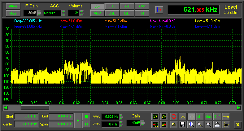
In addition to the narrow-band real-time spectrum analyzer in the demodulator panel, which shows the activity within a 20 kHz bandwidth, the WiNRADiO WR-G313 receiver also contains a wide-band spectrum analyzer which displays the frequency spectrum by fast sweeping. The displayed spectrum can cover the entire frequency range of the receiver. The minimum resolution bandwidth is less than 16 Hz (15.625 Hz).

This spectrum analyzer contains a number of advanced features, such as peak finding, display of minimum, maximum and differential sweeps, averaging, marker mode, spectra storage and retrieval, and other features.

This spectrum analyzer can be displayed in two different ways, selectable using the two yellow triangle buttons at bottom right of the receiver control panel.

The yellow triangle buttons provide entry to the spectrum analyzer.

Pressing the downward pointing arrow button causes the receiver control panel to extend downwards, to reveal a smaller version of the spectrum analyzer. If the upward pointing arrow button is pressed instead, this results in a larger spectrum analyzer window sliding upwards, totally replacing the receiver panel.

G313 Spectrum Analyzer (larger version)
WR-313 spectrum analyzer (smaller version, attached to the bottom of the receiver control panel).

The larger version, apart from offering a larger area for the spectrum graph, also contains a set of basic receiver controls at the top of the panel, in order to be able to conveniently operate the entire receiver in this mode:

G313 Spectrum Analyzer (larger version)

WR-313 spectrum analyzer (larger version, replacing the receiver control panel).

Real-time Spectrum Analyzer in WR-G313 Receiver

The real-time spectrum analyzer is just one of the many remarkable facilities of the WiNRADiO G313 receiver, providing the user with the ability to observe the received signal spectrum and its surroundings visually, and make appropriate adjustments of the filtering. This invaluable feature is largely absent in a conventional receiver, or available at a much higher price.

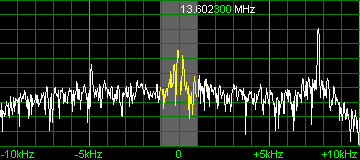
The real-time spectrum display shows the actual situation on the band within the "roofing filter" bandwidth of the receiver. This bandwidth is 15 kHz, but the spectrum display conveniently shows a somewhat wider area of 20 kHz. A central highlighted region of the spectrum changes corresponds to the IF (intermediate frequency) filter bandwidth selected by the user (continuously between 1 Hz to 15 kHz). This highlighted filter passband can be shifted, or its width altered, by simply dragging its center or edges using a mouse, to exactly match the received signal, maximize the signal-to-noise ratio and achieve the best possible signal clarity.

The real-time spectrum is zoomable, calibrated and able to display signal peaks with a resolution bandwidth of less than 16 Hz. A continuously-adjustable smoothing "video filter" is also included.

The spectrum can be also recorded and played back. This makes it possible to "re-receive" the same signal with different settings of the IF filtering and other parameters, and extract the maximum information out of a weak and noisy signal.


One of the demonstrable advantages of software-defined receivers is the enormous flexibility and a potential for development of new features, or innovative and improved implementations of existing features.

For example, the functions commonly referred to as IF shift or Passband Tuning are implemented in the WR-G313 receivers in an innovative and powerful way, which combines the real-time spectrum analyzer with the ability to adjust the IF filter passband precisely to suit the received signal.

In the WR-G313 receivers, this feature works in two possible modes:

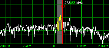
1. IF Shift (without BFO change) which makes it possible to tune the receiver to another frequency by simply dragging the entire filter passband over a peak of a visible signal.

2. Passband Tuning (with tandem BFO change), making it possible to adjust the filter position in SSB and CW modes without detuning the received station.

The first mode applies if the passband center is dragged using the left mouse button. The second mode is activated if the passband center is dragged using the right-mouse button (a PBT symbol will appear to indicate this mode).
Acoustic uses of Spectrum Analyzer

In acoustics, a spectrograph converts a sound wave into a sound spectrogram. The first acoustic spectrograph was developed during World War II at Bell Telephone Laboratories, and was widely used in speech science, acoustic phonetics and audiology research, before eventually being superseded by digital signal processing techniques. Now spectrum analyzers cover the acoustic range.

Operation of Spectrum Analyzer

Usually, a spectrum analyzer displays a power spectrum over a given frequency range in real time, changing the display as the properties of the signal change. There is a trade-off between how quickly the display can be updated and the frequency resolution, which is for example relevant for distinguishing frequency components that are close together. With a digital spectrum analyzer, the frequency resolution is Δν = 1 / T, the inverse of the time T over which the waveform is measured and Fourier transformed. With an analog spectrum analyzer, it is dependent on the bandwidth setting of the bandpass filter. However, an analog spectrum analyzer will not produce meaningful results if the filter bandwidth (in Hz) is smaller than the square root of the sweep speed (in Hz/s), which means that an analog spectrum analyzer can never beat a digital one in terms of frequency resolution for a given acquisition time. Choosing a wider bandpass filter will improve the signal-to-noise ratio at the expense of a decreased frequency resolution.

With Fourier transform analysis in a digital spectrum analyzer, it is necessary to sample the input signal with a sampling frequency νs that is at least twice the highest frequency that is present in the signal, due to the Nyquist limit. A Fourier transform will then produce a spectrum containing all frequencies from zero to νs / 2. This can place considerable demands on the required analog-to-digital converter and processing power for the Fourier transform. Often, one is only interested in a narrow frequency range, for example between 88 and 108 MHz, which would require at least a sampling frequency of 216 MHz, not counting the low-pass anti-aliasing filter. In such cases, it can be more economic to first use a superheterodyne receiver to transform the signal to a lower range, such as 8 to 28 MHz, and then sample the signal at 56 MHz. This is how an analog-digital-hybrid spectrum analyzer works.

For use with very weak signals, a pre-amplifier can be used, although harmonic and intermodulation distortion may lead to the creation of new frequency components that were not present in the original signal.

What is Spectrum Analyzer?

A spectrum analyzer or spectral analyzer is a device used to examine the spectral composition of some electrical, acoustic, or optical waveform. It may also measure the power spectrum.

There are analog and digital spectrum analyzers:

* An analog spectrum analyzer uses either a variable band-pass filter whose mid-frequency is automatically tuned (shifted, swept) through the range of frequencies of which the spectrum is to be measured or a superheterodyne receiver where the local oscillator is swept through a range of frequencies.
* A digital spectrum analyzer computes the discrete Fourier transform (DFT), a mathematical process that transforms a waveform into the components of its frequency spectrum.

Some spectrum analyzers (such as Tektronix's family of "real-time spectrum analyzers") use a hybrid technique where the incoming signal is first down-converted to a lower frequency using superheterodyne techniques and then analyzed using fast fourier transformation (FFT) techniques.